Engineering and Manufacturing of Water and Industrial Valves
Bailey Valve is an industry-leading internationally distributed valve manufacturer; providing a broad range of valve solutions to meet any water and industrial application.
Our Valve Models
The Bailey Valve sleeve valves has been designed to incorporate features that provide superior valve performance for inline, angle and terminal flow control & pressure reduction applications.
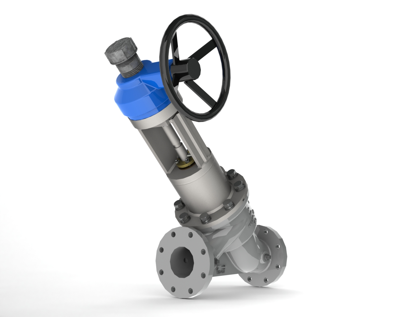
B-5
3 thru 12 inch Inline Y-pattern valve
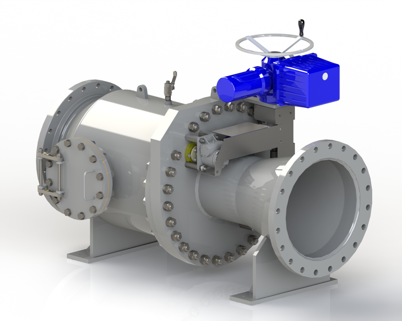
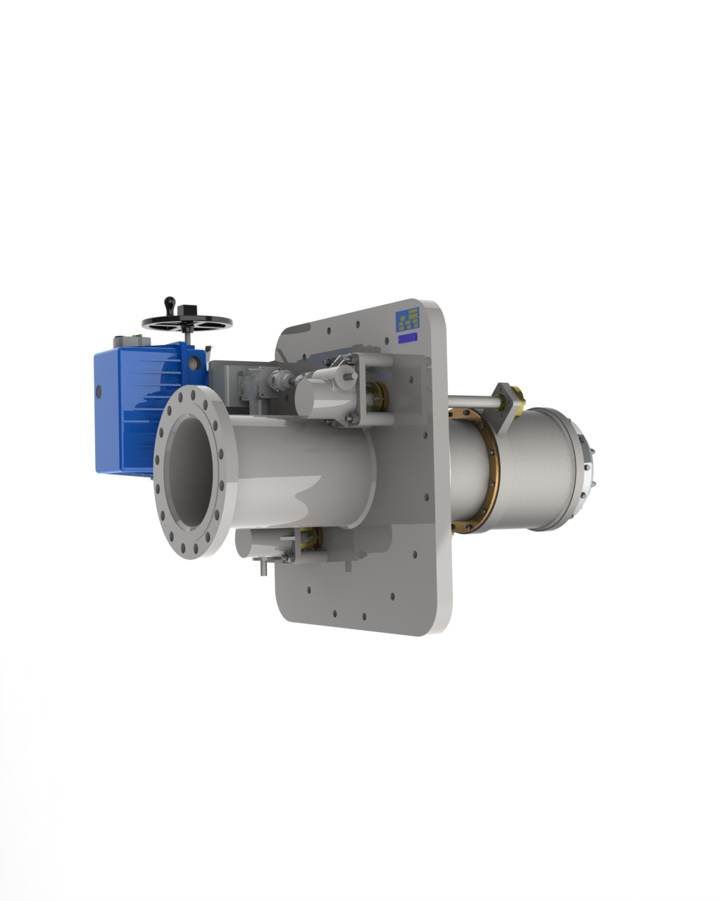
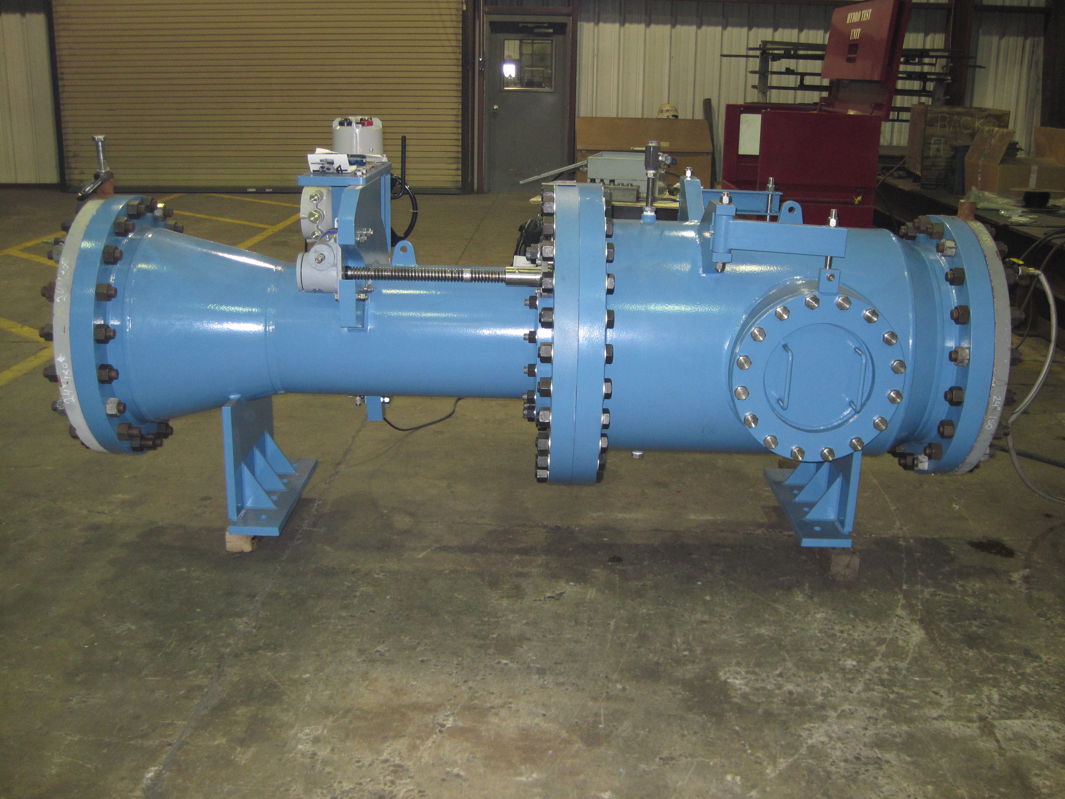
B-10
8 thur 72 inch Inline Valve
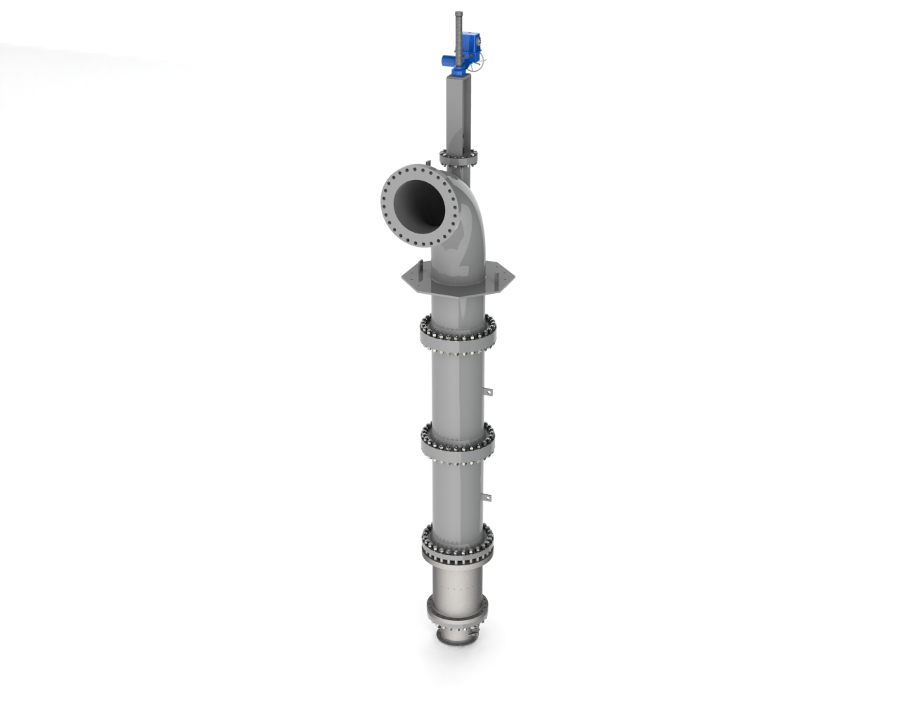
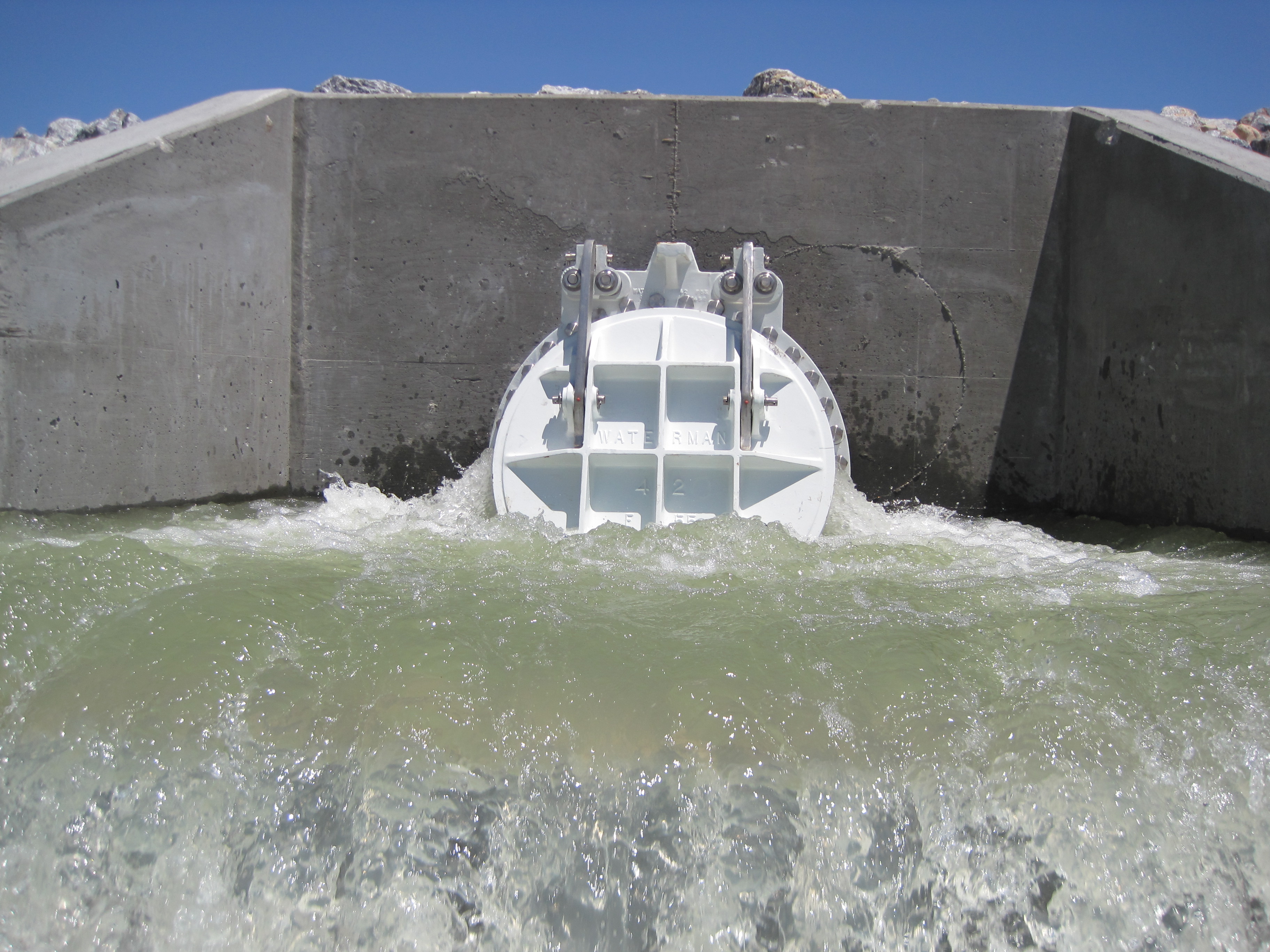
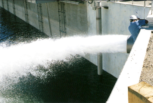
B-11
8 thur 72 inch Submerged discharge valve
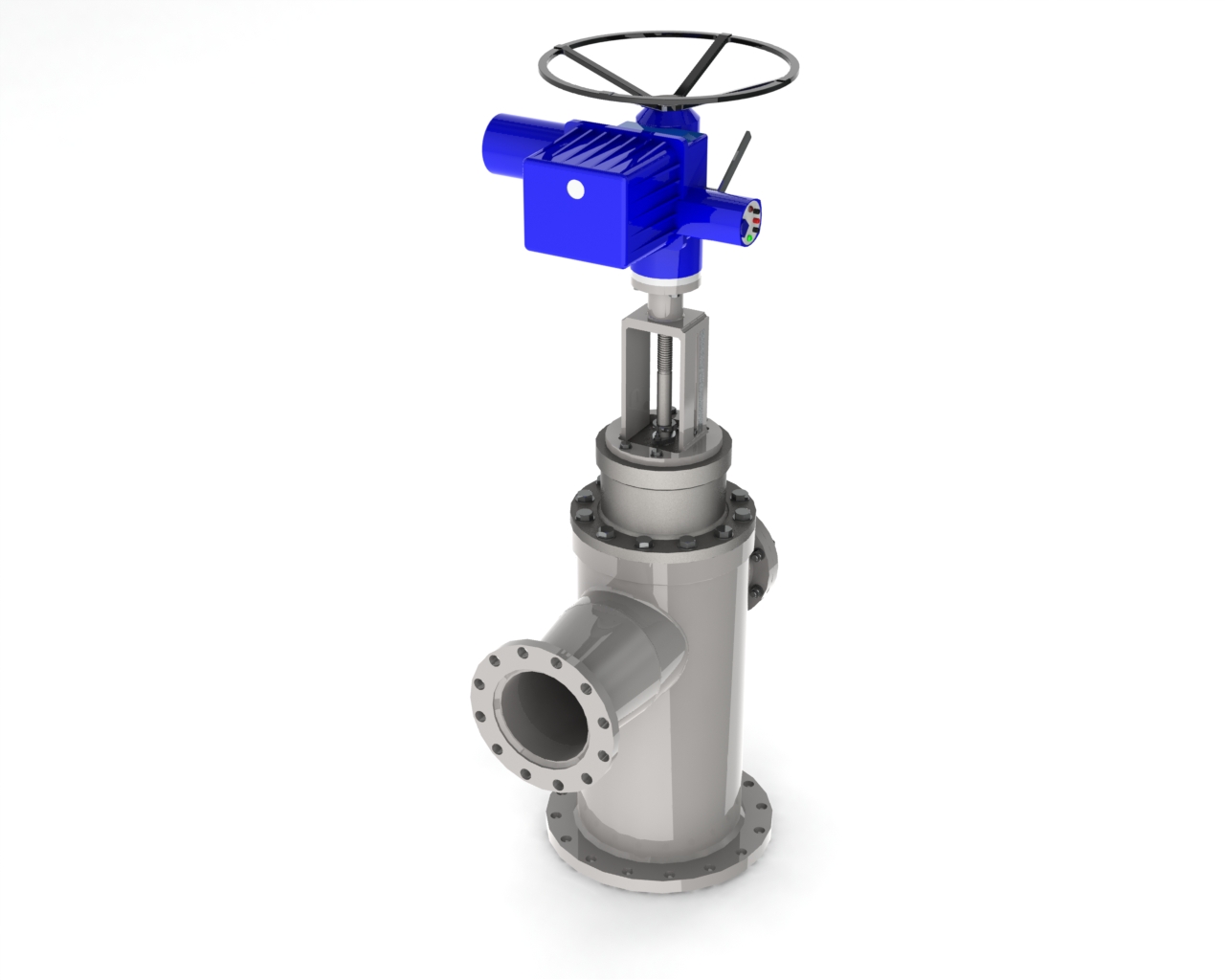
B-12
8 thru 66 inch 90 degree valve
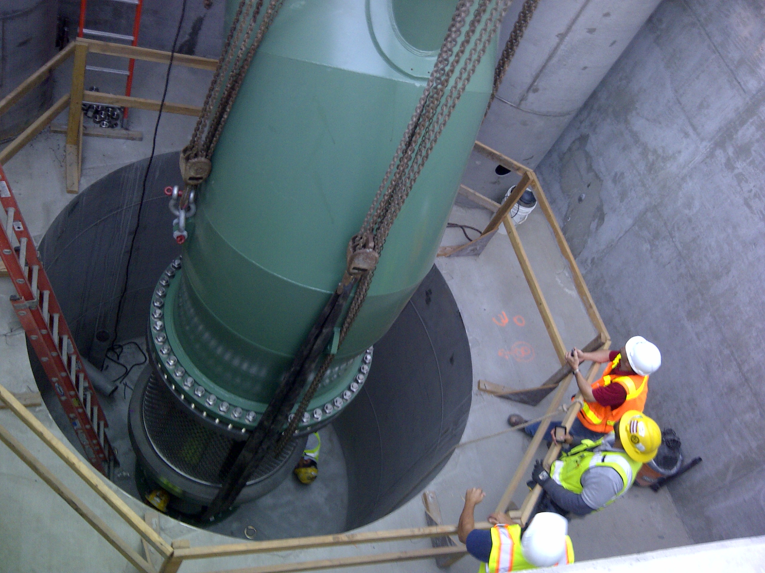
B-14
8 thru 72 inch wall mounted discharge valve
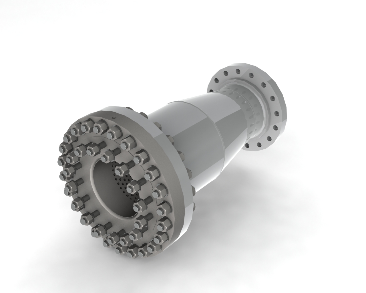
B-16
3 thru 72 inch Fixed orifice valve
Get in Touch
Address
264 W Fallbrook Ave #105
Fresno, CA 93711
Contact
Visit
M-F: 10am – 3pm
S-S: 9am – 2pm